
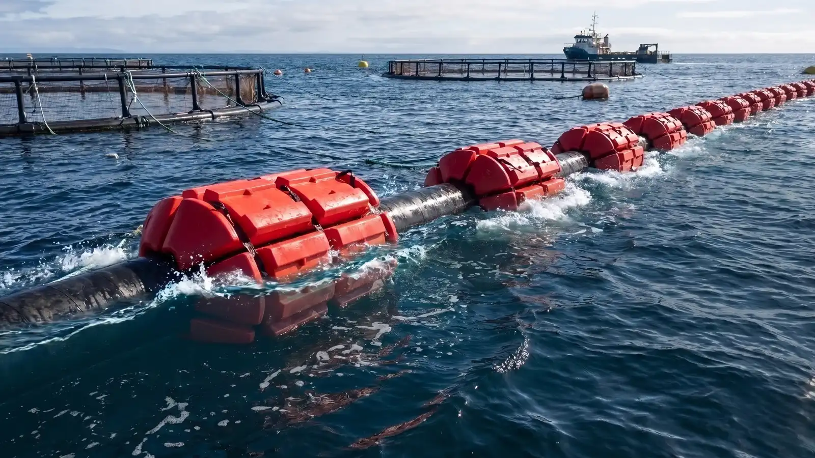
Install EZ Connect Floats only from the approved project layout and current manufacturer procedure. Field crews should receive the configured unit count, orientation, strap and ratchet arrangement, float-set locations, line restrictions, launch plan, inspection criteria, and stop-work conditions before assembly begins. “As tight as possible” and visual spacing estimates are not specifications.
- Quick Answer
- Step 1: Confirm Sizing and Spacing Before Mobilization
- Step 2: Stage Floats Along the Route Before Attachment
- Step 3: Attach Floats Starting From a Fixed Reference Point
- Step 4: Use Correct Attachment Technique for the Load Type
- Step 5: Verify Freeboard After Initial Deployment
- Step 6: Check Joint and Fitting Support Specifically
- Common Field Installation Mistakes
- Maintenance Checks During Ongoing Service
- Removal and Demobilization Technique
- Training Field Crews on Correct Technique
- What to Send EZ Connect Floats for a Project Review
- Frequently Asked Questions
- Related EZ Connect Resources
Quick Answer
Inspect the line, floats, straps, and ratchets; assemble each modular set at the approved location; keep hardware clear of joints, sharp edges, reinforcement, and prohibited support zones; use the specified tensioning method; then verify freeboard, sag, roll, slippage, line movement, and concentrated loads under the actual operating fill condition. Reinspect after startup and every significant change.
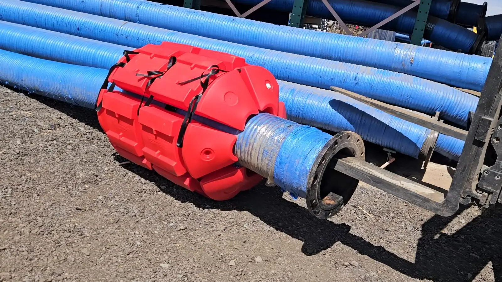
EZ Connect’s patented system uses individual polyethylene float units assembled around pipe, hose, cable, or umbilical with nylon straps and stainless-steel ratchets. Units can be added, removed, replaced, and reconfigured, but every new layout must be checked for fit, rated buoyancy, spacing, stability, hardware, line limits, and operating conditions.
Step 1: Confirm Sizing and Spacing Before Mobilization
Confirm the approved drawing or float schedule against the delivered pipe, hose, fittings, and float hardware. Verify outside diameter, wall or hose construction, operating and retained load, configured unit count, set spacing, local support, straps, ratchets, optional foam configuration, line-manufacturer restrictions, and revision status. Resolve discrepancies before field assembly.
Step 2: Stage Floats Along the Route Before Attachment
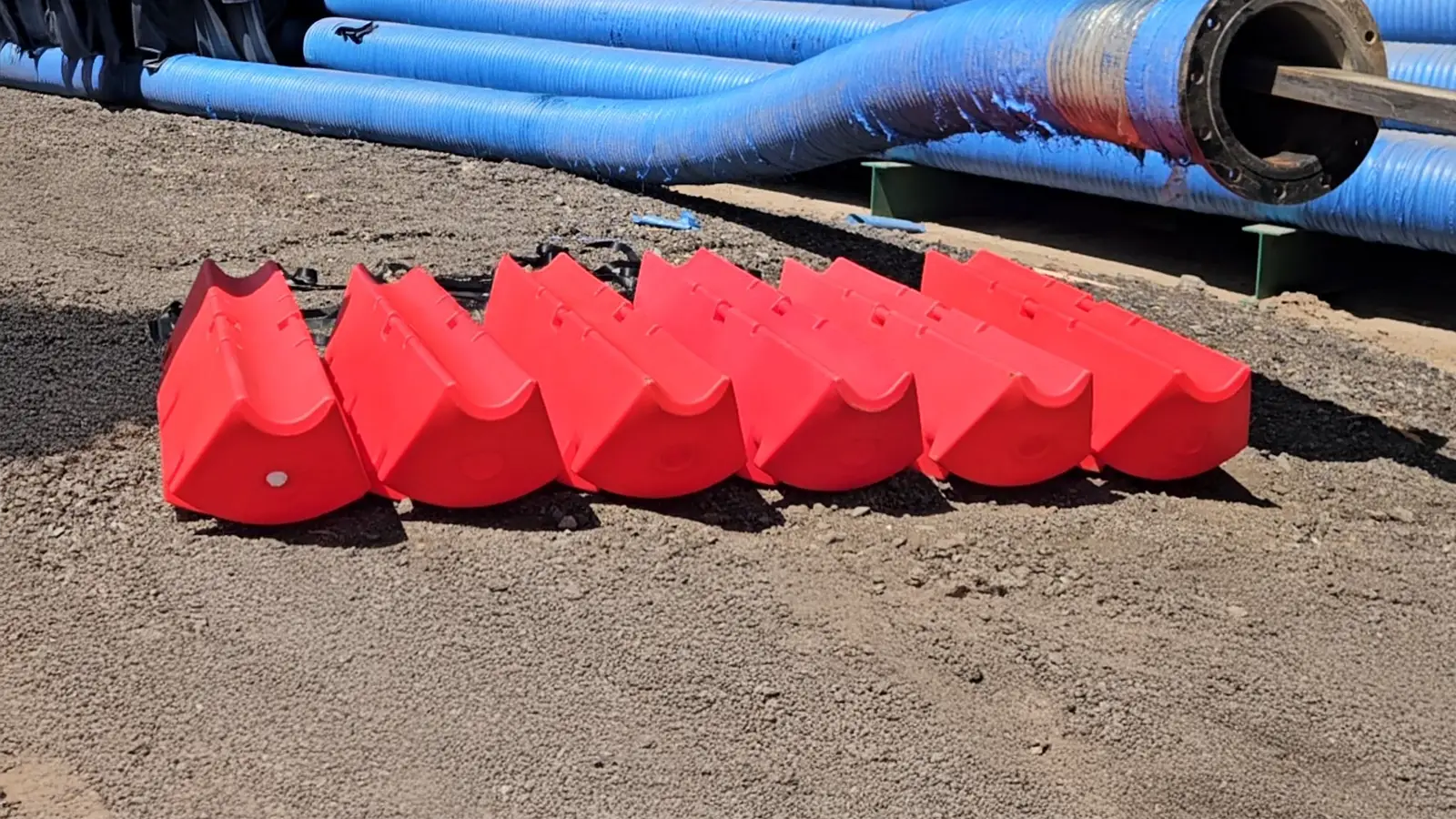
For longer pipe or hose runs, staging float units along the planned route before beginning attachment reduces the amount of back-and-forth movement needed during the actual installation sequence, particularly on runs crossing water or difficult terrain where repeated trips to a central staging area cost real time.
Step 3: Attach Floats Starting From a Fixed Reference Point
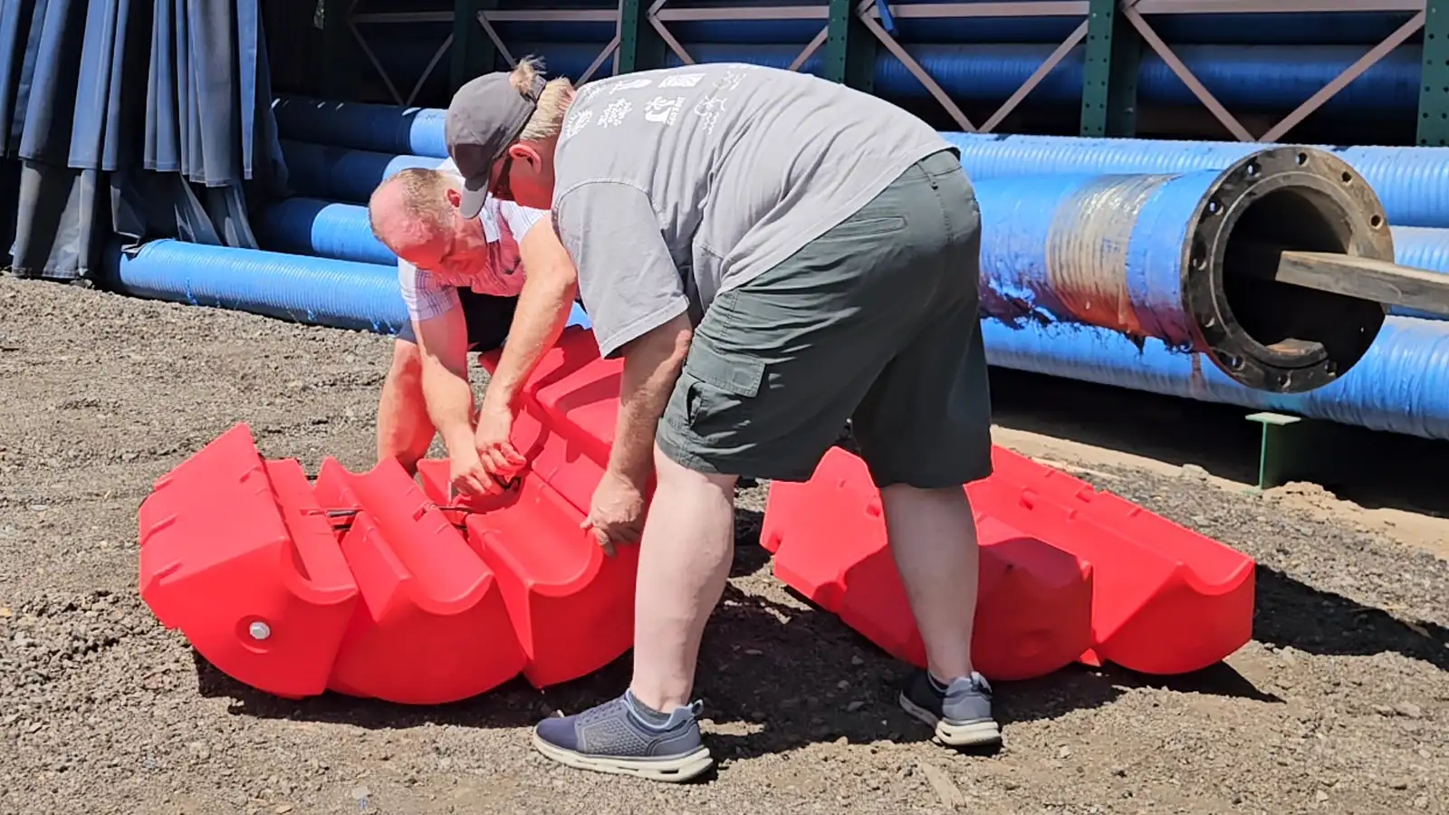
Use the approved drawing’s datum and measured set locations. A fixed reference can help control layout, but do not assume every spacing interval is uniform: couplings, valves, reducers, transitions, shore approaches, and heavy hardware may require purpose-positioned support. Mark or document locations so the installed layout can be inspected.
Step 4: Use Correct Attachment Technique for the Load Type
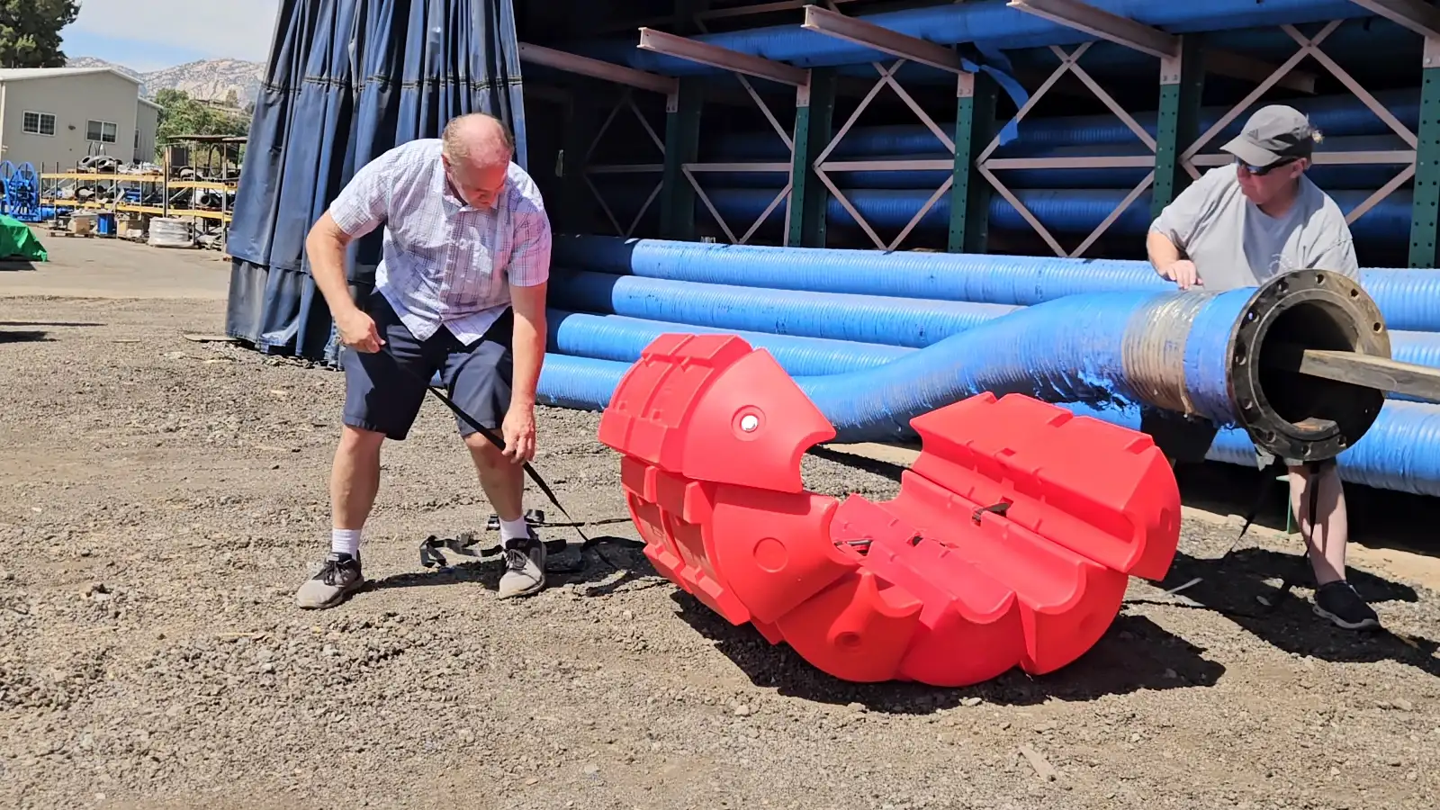
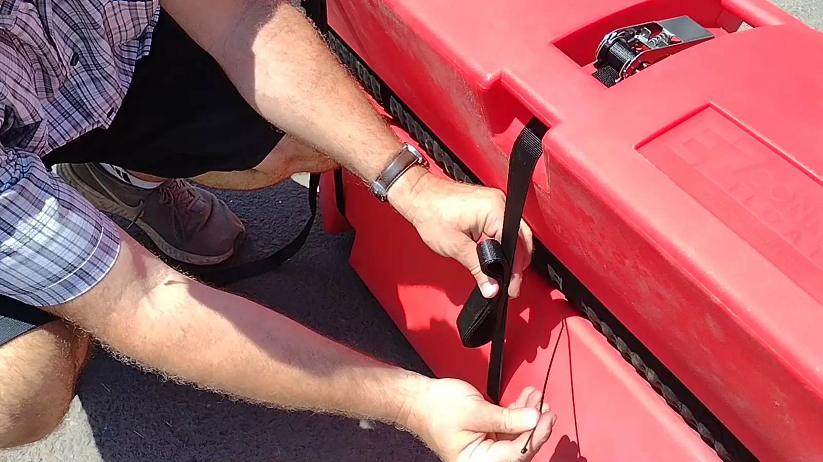
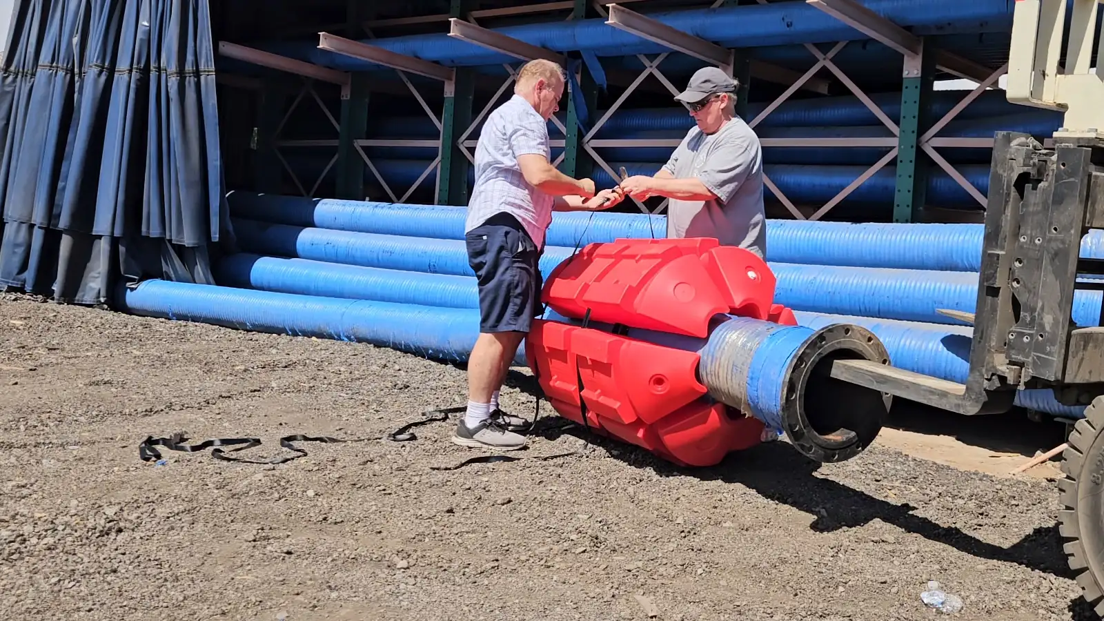
Assemble the specified number and orientation of modular units around the line using the approved nylon straps and stainless-steel ratchets. Follow the current EZ Connect and line-manufacturer procedure for strap routing, tightening, contact, and inspection. Do not improvise a “rigid” versus “flexible” tension rule, overtighten, crush the line, or leave a set loose enough to slide. Ratchets or installation tools may be required.
Step 5: Verify Freeboard After Initial Deployment
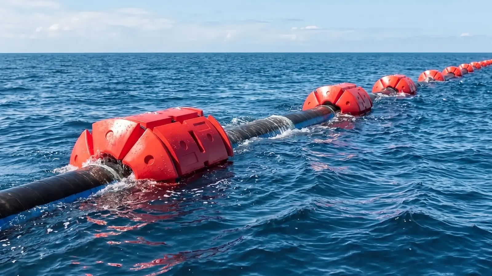
Launch, fill, pressurize, and commission the line only under the approved procedure. Check actual freeboard or submergence, roll, stability, sag, slippage, strap position, hose bend radius, pipe deflection, coupling support, route excursion, and contact with structures. Stop and investigate any mismatch before full operation; do not add random floats without reviewing the load and spacing plan.
Step 6: Check Joint and Fitting Support Specifically
Inspect every coupling, flange, valve, reducer, manifold, instrument, cable termination, booster connection, and pipe-to-hose transition. These components can create concentrated weight, stiffness changes, abrasion points, or movement. Additional support is not always required, but it must be evaluated and shown in the approved layout.
Common Field Installation Mistakes
- Installing from nominal diameter or memory instead of the current approved float schedule
- Estimating locations visually or carrying uniform spacing through heavy fittings and transitions
- Using fewer or differently oriented modular units than the approved configured set
- Routing straps over sharp edges, moving joints, cable jackets, hose reinforcement, or prohibited support zones
- Tightening “as much as possible,” improvising strap tension, or leaving sets able to slip
- Launching without checking floats, straps, ratchets, line condition, lifting points, and the JHA or marine-operations plan
- Verifying only the empty line instead of the actual operating and retained-load condition
- Failing to reinspect after startup, pressure changes, towing, relocation, impact, severe weather, or loss of freeboard
Maintenance Checks During Ongoing Service
Use the project’s documented inspection interval and acceptance criteria. Check float damage, water ingress indicators, straps, ratchets, corrosion, wear, slippage, roll, freeboard, line sag, bend radius, fittings, abrasion, anchors or restraints, route changes, and marine growth. Inspect again after startup, towing, relocation, storms, flood changes, debris impact, pressure changes, shutdown with retained material, or any visible change.
Removal and Demobilization Technique
Isolate and depressurize or drain the line as required, control stored energy, and follow the lift, retrieval, traffic, and environmental plan. Remove sets systematically without dropping hardware or damaging the line. Clean and inspect individual float units, straps, and ratchets; segregate damaged components; record service history; and store the inventory so the next project does not inherit an unverified configuration.
Training Field Crews on Correct Technique
Consistent installation quality across a contractor’s projects depends on field crews understanding not just the mechanical steps of attachment but the underlying reasons behind spacing and attachment technique differences between pipe and hose—a crew that understands why hose attachment needs to tolerate flex, for example, is less likely to over-tighten hose float attachment out of a reasonable-seeming instinct to “make sure it’s secure.” Building this understanding into standard field training, rather than relying purely on step-by-step instructions without the underlying reasoning, tends to produce more consistent installation quality across different crews and projects over time.
What to Send EZ Connect Floats for a Project Review
- Approved float schedule showing line sections, configured unit count, set spacing, local supports, hardware, and installation details
- Pipe or hose manufacturer data, outside diameter, construction, contents, pressure, bend/support limits, joints, fittings, transitions, and prohibited support zones
- Current EZ Connect installation instructions, strap and ratchet procedure, inspection criteria, spare parts, and damaged-unit disposition
- JHA or lift plan, staging and access, lifting/launch/retrieval method, line isolation and pressure controls, vessel or traffic plan, and environmental conditions
- Commissioning load case, acceptance checks, inspection interval, severe-weather and relocation triggers, demobilization method, crew training, schedule, and delivery location
Frequently Asked Questions
How tight should EZ Connect straps be?
Use the current manufacturer and line-approved procedure. “As tight as possible” is not a specification; incorrect tension can permit slippage or damage the supported line.
Can float spacing be measured from one fixed end?
Yes, when that matches the approved drawing. Also honor purpose-positioned support at fittings, transitions, and other concentrated loads rather than forcing a uniform interval.
What if actual freeboard does not match the design?
Stop and verify the fill condition, line and contents data, missing or misplaced sets, configured unit count, slippage, fittings, water conditions, and calculation basis before operating.
Do joints and fittings always need extra floats?
Not always, but every concentrated load and stiffness change needs a specific support review.
When should installed floats be rechecked?
At the project-defined interval and after startup, relocation, towing, severe weather, impact, pressure or load change, retained-material shutdown, damage, slippage, or loss of freeboard.
Related EZ Connect Resources
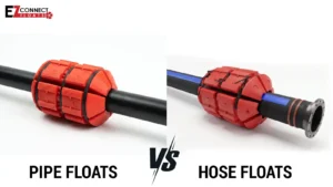
Pipe Float vs. Hose Float: What’s the Real Difference?
This guide explains how dredge pipe floats work, how to size and space them, how the main float types compare, and where clamp-on HDPE dredge pipe floats fit — so a floating dredge pipeline stays on the surface through the whole job.
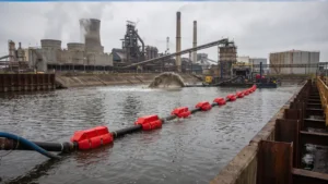
Floats for Wastewater Bypass and Temporary Pumping Systems
This guide explains how dredge pipe floats work, how to size and space them, how the main float types compare, and where clamp-on HDPE dredge pipe floats fit — so a floating dredge pipeline stays on the surface through the whole job.
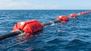
Floats for Marine Construction: Complete Buyer’s Guide
This guide explains how dredge pipe floats work, how to size and space them, how the main float types compare, and where clamp-on HDPE dredge pipe floats fit — so a floating dredge pipeline stays on the surface through the whole job.